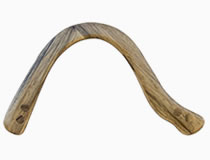
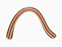
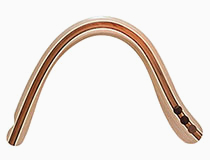
The material of this article is for informational purposes and is based on data from the profile aerodynamics analysis program. The interpretation of the data is subjective and may not be accurate.
Modifying the shape of the boomerang profile is a fine-tuning, and it should be applied if your boomerang is already flying correctly, and you need to adjust its characteristics a little. At the same time, you need to understand exactly how this or that change affects the flight path. For test trials, it is better to use temporary solutions.
Next, let's look at how the change in the shape of the profile affects the generated lift and drag. Parameters for calculations are the basic settings of the program.
Terms
Within the framework of this article, for simplification, the following definitions and terms are used:
-
Lifting force: the symbol of the lifting force coefficient (Cl). The graphs show exactly the lift coefficient. The actual lifting force is calculated using formulas with a variety of coefficients and parameters.
-
Drag: The symbol of the drag coefficient (Cd).
-
Wing angle of attack: the angle between the chord (the line at the farthest points of the profile) and the vector of the incoming air flow (alpha).

The convexity of the upper bevel of the leading edge of the profile.
For example, three identical profiles, differing in the convexity of the upper bevel of the leading edge.
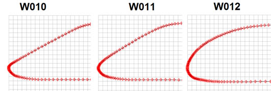
The profile W012 has the "plumpest" edge, W010 is the flattest, and W011 is a kind of "intermediate" version.
On the graph, where the dependence of the lift coefficients (Cl) and the angle of attack of the wing (alpha) is displayed, it can be seen that, at zero angle of attack, W011 has the largest lift coefficient.
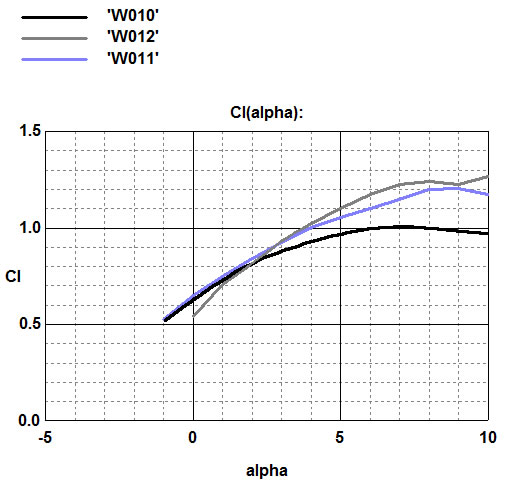
A plumper edge at zero angle has less lift, but also minimal drag, and with an increase in the angle of attack generates more lift than profiles with a beveled edge.
A beveled leading edge can slightly increase lift, but also significantly increase drag.
In the following example, the W020 profile is a modification of the W021 profile, with a more convex upper edge.
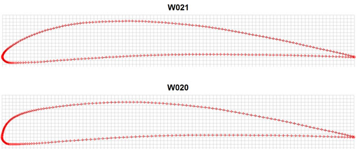
The excessively convex upper edge of the W020 profile leads only to an increase in drag at all angles of attack, without increasing lift.
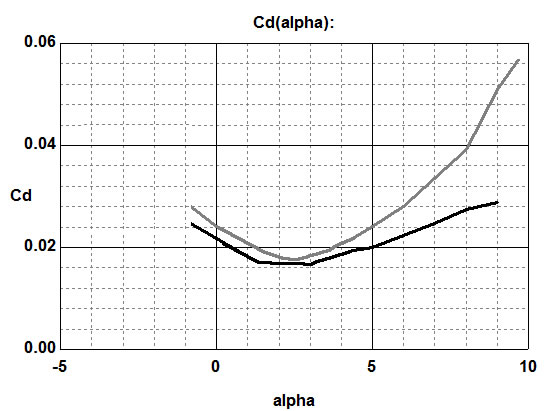
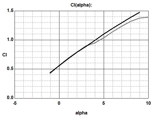
The length of the upper bevel of the leading edge of the profile.
Two identical profiles, differing in the length of the upper bevel.
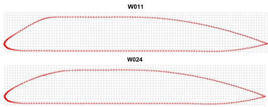
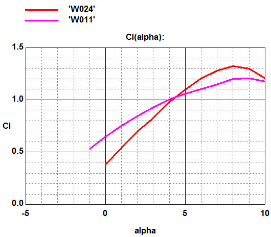
The elongation of the bevel at W024 greatly reduces the lifting force at zero angles of attack, but also seriously reduces drag at all angles.
The lower bevel of the leading edge of the profile.
For example, there are two profiles that differ in the lower bevel of the leading edge.
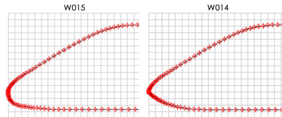
Profile W015 has a smoother bend of the edge (a more "blunt" nose). W014 with a sharper (sharp) the bevel of the edge.
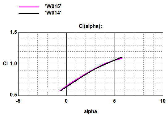
Judging by the graph, straightening the lower edge slightly reduces the lift, or vice versa, a more "blunt" edge from below slightly increases the lift of the wing.
Here is another example. Attention to the blue graph, only this profile has been modified.
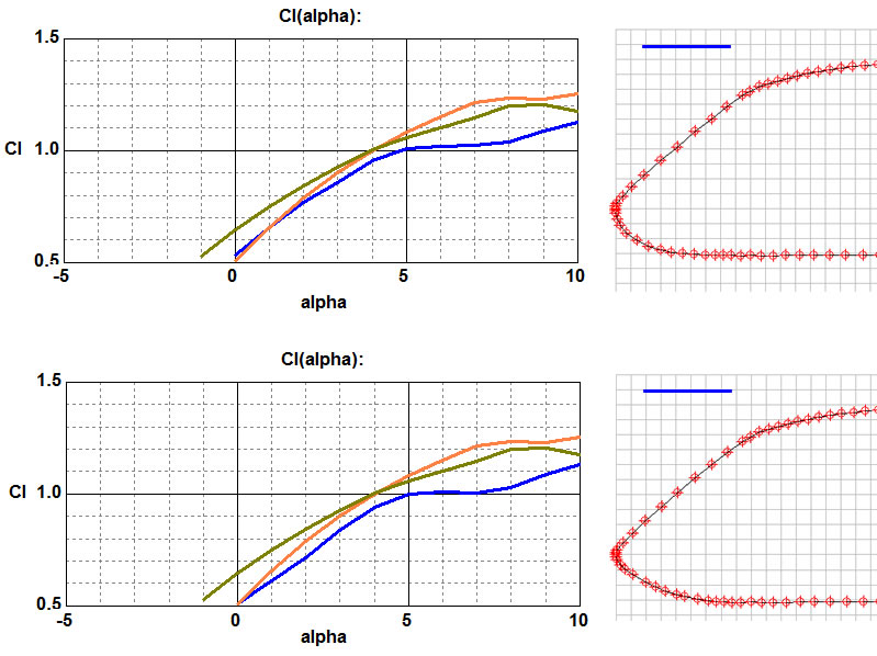
In this example, it can also be seen that the lifting force decreases slightly with a more "sharp" lower edge.
Upper bevel of the rear edge of the profile
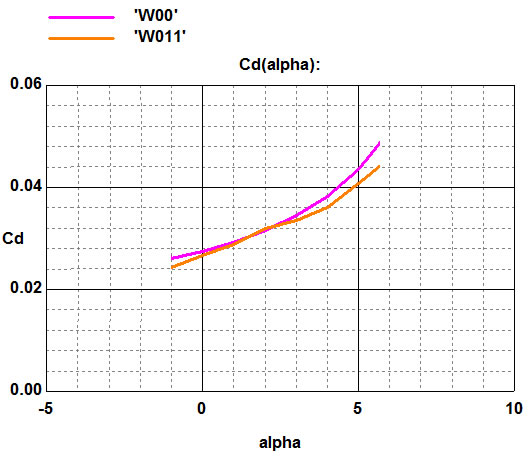
The W011 profile has a more elongated edge bevel than the identical W00.
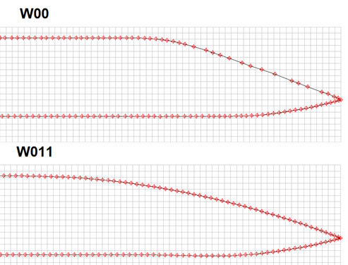
On the graph of the dependence of the coefficients of lift (Cl) and the angle of attack of the wing (alpha), at zero angle of attack, the profile W011 generates more lift than W00, therefore, the elongation of the bevel leads to an increase in lift.
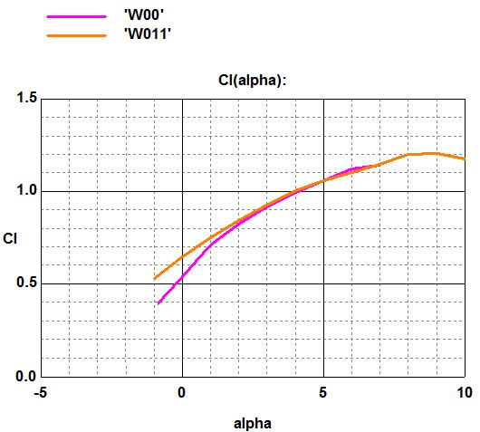
With an increase in the angle of attack of the wing, the characteristics are aligned.
Profile W011, at different angles of attack, has less drag (Cd).
Lower bevel of the rear edge of the profile.
For example, there are two profiles that differ in the length of the lower bevel of the trailing edge.
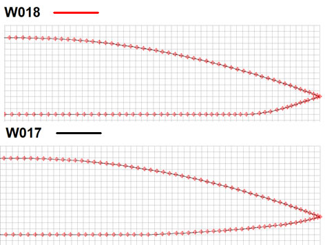
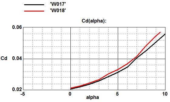
The W017 profile has a more elongated rear lower bevel than the W018.
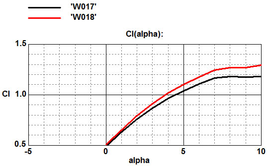
The graphs show that the elongation of the bevel (W017) leads to a slight decrease in lift, but also reduces drag.
