The material of this article is for informational purposes and is based on data from the profile aerodynamics analysis program. The interpretation of the data is subjective and may not be accurate.
This publication is a continuation of the article The effect of profile edges on the aerodynamic characteristics of the boomerang wing. The basic terms and definitions are also described there.
Chord – a line connecting the farthest points of the profile. The position of the chord affects the characteristics and efficiency of the wing. When setting up the boomerang, it is possible to change the position of the chord within certain limits to obtain the required characteristics.
The position of the chord in height
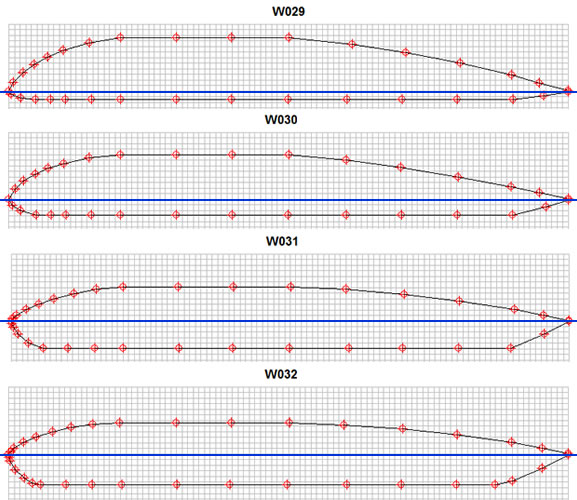
Conditions: the position of the chord is horizontal; only the position of the chord changes along the height of the profile, without increasing the length of the bevels of the edges.
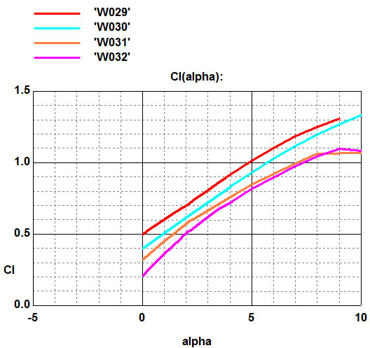
The profile W029 has the lowest chord position, W032 the highest.
The graph of the dependence of the lift coefficient (Cl) on the angle of attack of the wing (alpha) shows an increase in lift with a decrease in the position of the chord. Increasing the position of the chord reduces the lifting force, up to negative values. The drag, with an increase in the chord, in this case, also increases.
Changing the leading edge
Conditions: the position of the chord changes due to modification of the leading edge, without increasing the length of the bevels of the edge.
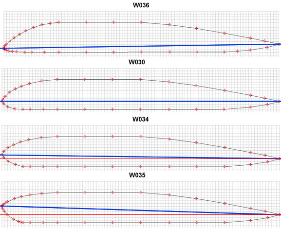
Profile W036 has the lowest position of the tip of the edge (nose), then as it rises: W030, W034, W035. The position of the chord (the blue line in the figure) changes accordingly.
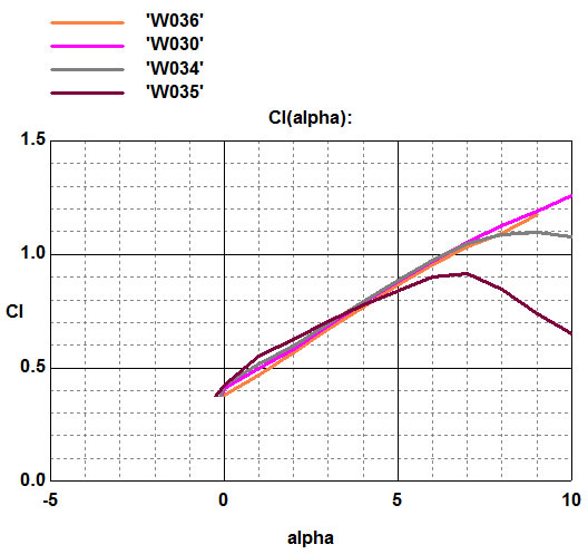
The graph of the dependence of the lift coefficient (Cl) on the angle of attack of the wing (alpha) shows a slight change in lift.
In this case, the zero value of the angle of attack alpha on the graph corresponds to the horizontal position of the wing (as in the figure). I.e., for example, W035 in the position as in the figure already has a positive angle of attack. If you make a calculation in the program by lowering the chord to the zero position (combining the blue line with the red one, thereby turning the wing), then the lifting force, at zero angle of attack, will be much less.
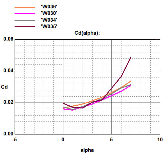
On W034 and W035, with an increase in the angle of attack, apparently, the flow from the wing is disrupted earlier than others, with a strong subsequent increase in drag.
Changing the trailing edge
Conditions: the position of the chord changes due to modification of the trailing edge, without increasing the length of the bevels of the edge.
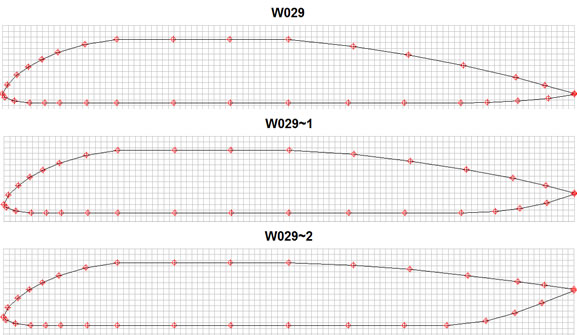
The profile W029 has the lowest position of the tip of the edge (tail), then as it rises: W029-1, W029-2.
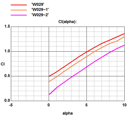
The graph of the dependence of the lift coefficient (Cl) on the angle of attack of the wing (alpha) shows a large change in lift from the position of the trailing edge.
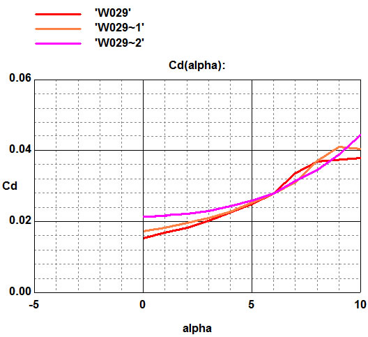
The W029 generates the largest lift, and the minimum drag, as it has the narrowest trailing edge.
